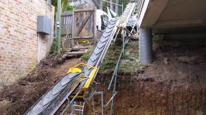
The Shifta range of conveyor belts are great machines to hire if you're looking to move a lot of muck or earth, and they can be daisy-chained together to form long runs and move earth where you need it to go. You can link many conveyors together, for example 20x 5m conveyors providing 100m length!
Components
First, let's get familiar with the components of hired conveyors:


1. Power / Comms link INPUT
2. Bogey locking pin
3. Emergency stop
4. Forward/ Stop/ Reverse/ Twin Speed
5. Power / Comms link OUTPUT
6. Adjuster pivot bolt
7. Conveyor trestle
8. Forklift pockets
9. Forward/ Stop/ Link/ Voltage indicator
10. Operator manual QR Code
11. Wheels 6: Top adjuster
12. Drive drum
13. Hopper
Controls
There are two sets of controls on these conveyors.

This bank of controls features E-stop, fast/slow speed, reverse, stop, and forward.

The second control bank includes forward, stop, conveyor link activator, voltage indicator, and an E-stop.
Setting up the Conveyors
1. Fold wheels down from transport position. Lift base of machine, pull black locking pin. Rotate wheels into position and let go of pin. The pin should engage into locking plate. Lower machine safely onto the ground. Do not drop machine.


2. Manoeuvre the conveyor into position using correct manual handling techniques. Utilise the handles at the top and base of the conveyor to maximise grip when moving. When in position locate the conveyor onto the supplied trestle. This will allow the transported material to drop directly into the next conveyors hopper. Ensure that the brakes are applied at this point.

3. When in position, fit the hopper to base of machine. Align the slots both sides so they line up with the mounting pins. Pins are shown in red. Push hopper toward top of machine until the front mounting pin stops at the base of the slot. Then push down to lock hopper in place.

4. Once machine is in place. Plug in power supply at the base of the conveyor and start pre-operation checks

5. Once power is applied to the conveyor, the stop button will illuminate. The voltage indicator will also display the supply voltage. This indicates that the conveyor is ready to run.

6. The conveyor is now ready to use. Press FWD to run the conveyor. The buzzer will sound for 2 seconds, then the belt will move. If loading with a digger or skid steer, take care not to overload the hopper.

7. When linking additional units, place the first conveyor in the line and work forwards from this unit. Repeat steps 1-6 of this manual for each conveyor. Take care to ensure the previous conveyor is discharging into the centre of the hopper of the next conveyor in the line. This will help minimise overspill.

8. When linking multiple units, it is a two-person operation. First start with the power supply. Connect the power to the first conveyor.
9. Then using the power linking lead supplied, plug the linking lead into the power output socket on the end of the conveyor then into the power input socket of the next conveyor. Up to 5 conveyors can be powered off a single 5kVA supply.

Ensure the power lead cannot get tangled in the moving belt.
Do not connect the power linking leads whilst the conveyor is in use.
10. Once the conveyor controls are linked, begin the process of switching the conveyors into LINK mode.
Every conveyor must have the LINK button pressed in and illuminated. Except the last conveyor in the run. The last conveyor in a chain must have the LINK button in the out position and not illuminated.

link button switched off

link button switched on
Example: If 5 conveyors have the controls linked. The first 4 conveyors will have the LINK button pressed and illuminated. The last conveyor in the chain will have the LINK button out and not illuminated.
12. The conveyor system will now be able to start and stop from any conveyor along the line. The only functions that are not linked are the FAST/ SLOW function and the REVERSE function.
The FAST/ SLOW function is not included in the control link due to varying angles being deployed. The steeper conveyors will generally run at a faster speed than the flat conveyors. This is to minimise any build up accumulating in the hopper.
13. When the Shifta conveyors are used in link function extreme care should be used if the discharge of the run cannot be seen by the operator. This is also applicable if any conveyor cannot be seen at any point of the chain.
Each conveyor is equipped with an audible buzzer the sounds before the belt moves. This ensures that any personnel near the unit upon start up have time to exit any hazard zones and operate the E-Stop.
If the entire chain of conveyors is not visible to the operator, a site-specific risk assessment must be carried out to assess the potential hazards that may occur from the operation.
If the discharge is not visible to the operator, the two-person team operating the conveyor chain must ensure that a hazardous situation cannot occur during the operation of the conveyors. This also requires a site-specific risk assessment to be carried out to assess the potential hazards that may occur from their operation.
14. If a blockage occurs during the LINK operation. Stop the conveyors. The blockage can then be identified and assessed. To aid unblocking individual conveyors, the reverse function is not linked when part of a chain of conveyors. To reverse a single conveyor, hold the reverse button on the blocked unit and the belt will reverse. It is a dead man switch so it will only function when it is pressed.
Once the blockage has been cleared, the linked units will function as normal from any conveyor control.
Disassembling the conveyor chain
- When disassembling the run of conveyors after a project. Plan the routes for each conveyor and use correct manual handling techniques. Clean each conveyor before transporting.
- Disconnect power before attempting to move any SHIFTA conveyor
- When the SHIFTA conveyors are stored. Fold the wheel bogey up into the locked position and stack the units to maximise space. Maximum 5 high.
Function Test Tasks for Multiple Conveyors
- Setup the conveyors in a test area that is firm, level, and safe. Plug power into the 110v 32A socket of first conveyor in the chain.
- Observe the centre red button on control box. This button should be illuminated. The voltage indicator on the left-hand side of the conveyor will display the input voltage.
- Ensure that the link procedure has been followed correctly.
At the controls:
- Press the emergency stop button on the side of the first conveyor. The centre red button on every conveyor will slowly flash indicating a stop circuit function.
- Press forward and reverse buttons on any conveyor. Belts should not move.
- Release emergency stop by rotating it clockwise until it releases and clicks out. All red lights should return to being permanently illuminated.
- Press the emergency stop button on the side of another conveyor in the line. The centre red button on all conveyors should flash slowly indicating a stop circuit function.
- Press forward and reverse buttons. Belt should not move.
- Release emergency stop by rotating it clockwise until it releases and clicks out. Red light should return to being permanently illuminated.
Test the forward and reverse functions:
- Press the forward button on first conveyor. Buzzer will sound for 2 seconds. All belts will move forwards.
- Press the fast/ slow button. Belt will speed up on the single conveyor
- Wait 5 sec then press the fast/ slow button. Belt on single conveyor will slow down.
- Press the centre stop button. All belts belt will stop.
- Press and hold the reverse button. The belt should move in reverse after 2 seconds. (Only the conveyor being operated will move in reverse)
- Release reverse button. The belt should stop moving.
And that's it! Enjoy saving time & getting the job done faster with less manual handling.